Introduction to the Coordinate System
The coordinate system in Model Builder is a Cartesian coordinate system (X, Y, Z). It is intuitive and versatile to facilitate 3D modeling.
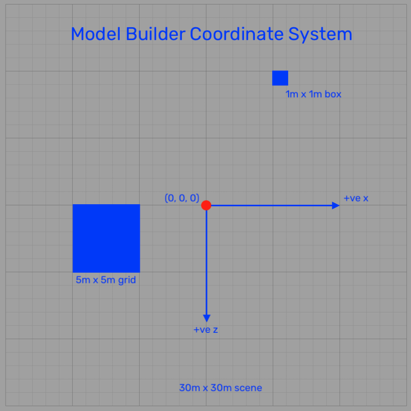
This system defines the position of every object in 3D space using three axes:
-
X-Axis (Red):
- Represents the horizontal direction.
- Positive values move right; negative values move left.
-
Y-Axis (Green):
- Represents the vertical direction.
- Positive values move up; negative values move down.
-
Z-Axis (Blue):
- Represents depth (forward/backward direction).
- Positive values move forward; negative values move backward.
Each axis intersects at the origin (0, 0, 0), which is the central reference point in the space.
How the Coordinate System Translates into Model Builder
In Model Builder, every element you create, from basic shapes to complex assemblies, is positioned and oriented using the X, Y, and Z coordinates. Here are some key concepts:
-
Grid System:
- The workspace is overlaid with a grid to aid in alignment and scaling.
- Small grids represent 1m x 1m, while larger grids span 5m x 5m.
-
Units and Measurements:
- The coordinate system uses meters as the default unit of measurement, ensuring consistency and compatibility with real-world dimensions.
-
Positioning Objects:
- The position of an object is defined by its X, Y, and Z coordinates relative to the origin.
- Example: A column placed at (5, 0, 10) will be 5 meters to the right, 0 meters vertically, and 10 meters forward from the origin.
-
Orientation and Rotation:
- Objects can be rotated around any of the three axes using angles (typically measured in degrees).
- Example: Rotating a beam by 90 degrees around the Y-axis will align it perpendicular to its original position.
-
Scaling:
- Objects can be scaled independently along the X, Y, and Z axes.
- Example: Scaling a cube by (2, 1, 1) doubles its width while keeping its height and depth constant.
Different Views of the Coordinate System
Understanding how to view your model from different perspectives is crucial for precise design. Model Builder offers several predefined views:
- Isometric View:
- Provides a 3D perspective where all three axes are visible.
- Ideal for visualizing the overall structure and layout of the model.
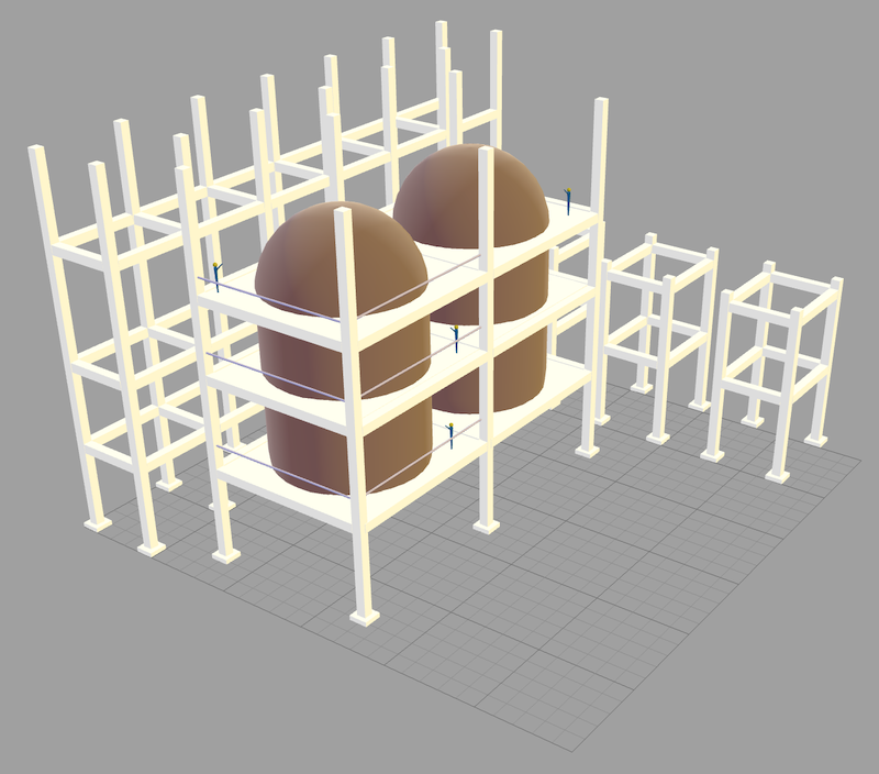
- View from X-Axis:
- Shows the model as viewed along the X-axis.
- Useful for inspecting depth and vertical alignment (Y and Z dimensions).
- Clicking the red dot aligns the model along the X-axis.
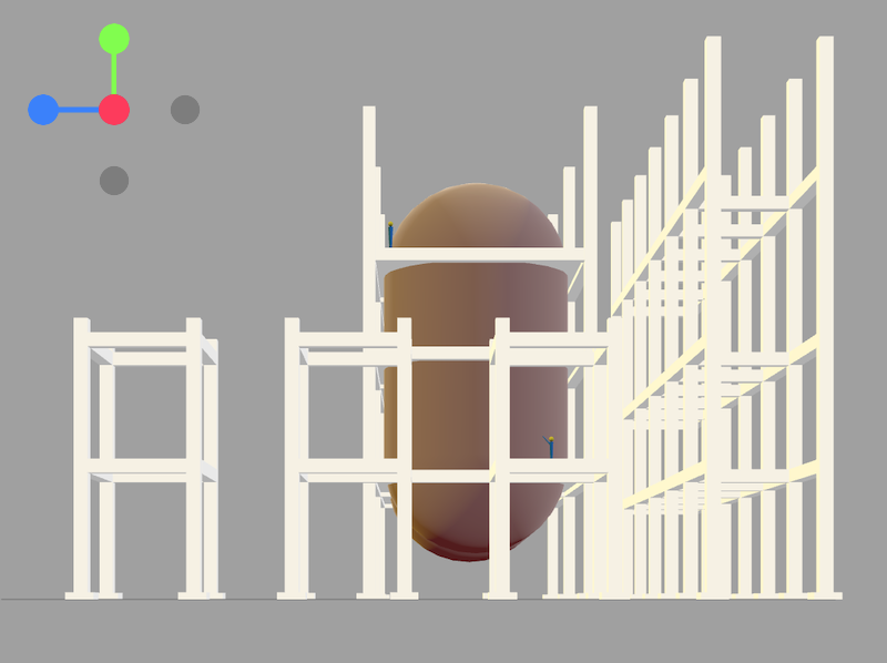
- View from Y-Axis:
- Displays the model as viewed along the Y-axis.
- Useful for inspecting width and depth (X and Z dimensions).
- Clicking the green dot aligns the model along the Y-axis.
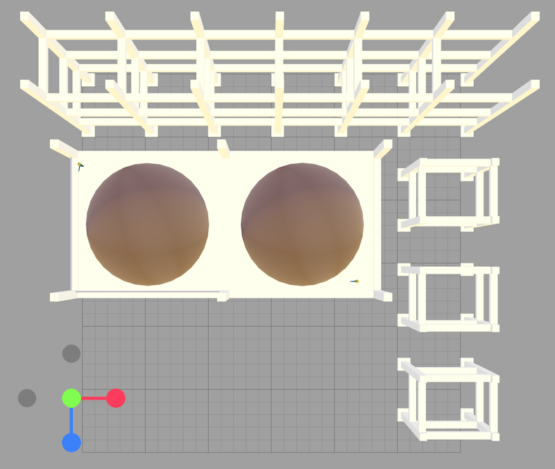
- View from Z-Axis:
- Presents the model as viewed along the Z-axis.
- Useful for inspecting width and height (X and Y dimensions).
- Clicking the blue dot aligns the model along the Z-axis.
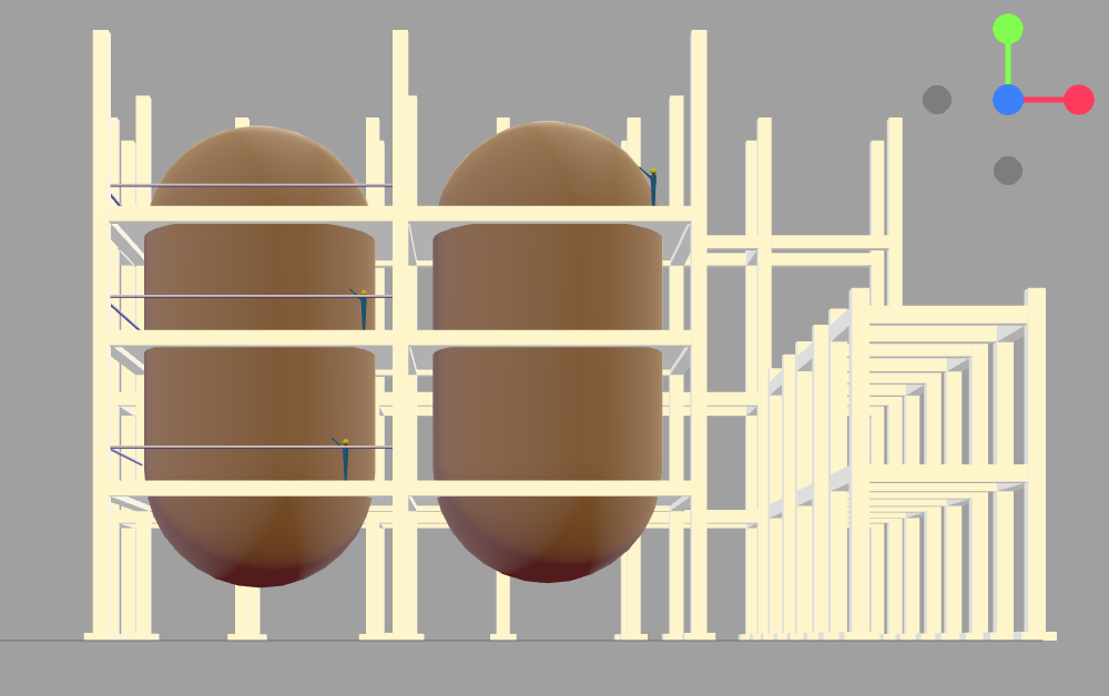
Each of these views provides unique insights into your model’s dimensions and alignments, making it easier to identify and correct errors during the design process.
Working with the Coordinate System
Here are some practical tips for working efficiently with the Model Builder coordinate system:
-
Start at the Origin:
- When creating new elements, begin at the origin (0, 0, 0) to simplify alignment and grouping.
-
Understand Local vs. Global Coordinates:
- Global coordinates refer to an object’s position in the workspace.
- Local coordinates refer to an object’s position relative to its parent group or structure.
-
Group Elements Early:
- Grouping related elements (e.g., a footing and column) simplifies positioning and transformation.
-
Experiment with Views:
- Use different camera views (top, front, side) to gain a better perspective on your model’s positioning.
Advantages of Using this Coordinate System
-
Consistency: Ensures compatibility with industry-standard 3D modeling practices.
-
Flexibility: The system supports complex transformations like rotations, scaling, and hierarchical grouping.
-
Real-World Mapping: Using meters as the default unit allows seamless integration with engineering and architectural projects.
-
Visual Feedback: The color-coded axes and grid system provide immediate visual feedback, reducing errors during modeling.
Conclusion
The coordinate system in Model Builder is the foundation for creating accurate and organized 3D models. By understanding and utilizing the X, Y, and Z axes effectively, you can design complex structures with precision and confidence. Whether you’re a beginner or an experienced modeller, mastering this system will elevate your workflow and unlock the full potential of the app.


